Run your first BLE application
This documentation aims to introduce the procedure of building the program, generating the binary image and programming the flash and make necessary explanation on flash parameters configuration and basic concepts of program building outcome.
Common steps of building and running a program
- Compile all source files and link all of the object files to a single (AXF)ELF file
- Generate raw binary(hex) file,assembly file and map file from ELF. Only user program image is included in the raw binary(hex) file.
- Configure the bootloader to adapt for flash.
- Merge raw binary(hex) with bootloader.
- Download the hex file with bootloader to flash.
- Reset the board, then the program will run.
Flash parameters configuration for bootloader
Before building an application, we should configure some parameters to bootloader to enable booting and executing from flash. The configuration file config.ini is in [SDK DIR]\tools\image_tool_v2\. This configuration file will be used by executable boot_ram_config.exe to set corresponding parameters in boot_ram.hex during each build.
The file looks like:
[App]
ota_base = 0x40000
data_base = 0x70000
[Flash]
total_size = 0x80000
[Multi_Read]
;Dual_Output_Read_Mode(0x3B),Quad_Output_Read_Mode(0x6B),Dual_IO_Read_Mode(0xBB),Quad_IO_Read_Mode(0xEB)
cmd = 0x6B
;0:Both_Standard_SPI_Mode,1:Instruction_Standard_Address_Specific,2:Both_Specific_Mode
trans_type = 0
wait_cycles = 8
;1:Dual_SPI_Format,2:Quad_SPI_Format
dual_quad = 2
[Quad_Enable_Read]
cmd = 0x35
quad_bit_offset = 1
status_length = 1
[Quad_Enable_Write]
cmd = 0x01
quad_bit_offset = 9
status_length = 2
Fisrt of all, set Flash:total_size to the actucal value and App:ota_base and App:data_base to appropriate value. Refer to Memory map and Image structure for detailed description of App:ota_base and App:data_base.
Then configure [Multi_Read] [Quad_Enable_Read] [Quad_Enable_Write] according to Flash datasheet.
Typical configuration for [Multi_Read]:
| cmd | 0x3b | 0x6b | 0xbb | 0xeb |
| trans_type | 0 | 0 | 1 | 1 |
| wait_cycles | 8 | 8 | 4 | 4 |
| dual_quad | 1 | 2 | 1 | 2 |
[Quad_Enable_Read] [Quad_Enable_Write] configurations are only valid for Quad Flash.
Flash Quad Enable Config Guide
We’ll use the datasheet of Quad Nor Flash Winbond W25Q80DV as an example to illustrate how to set [Quad_Enable_Read] and [Quad_Enable_Write].
- [Quad_Enable_Read]
This configuration is used to tell the bootloader the way to get Quad status of flash. The 9th bit (S9) of ststus register, non-volatile QE bit, indicating whether the flash allows Quad operation can be read by Read Status Register command.
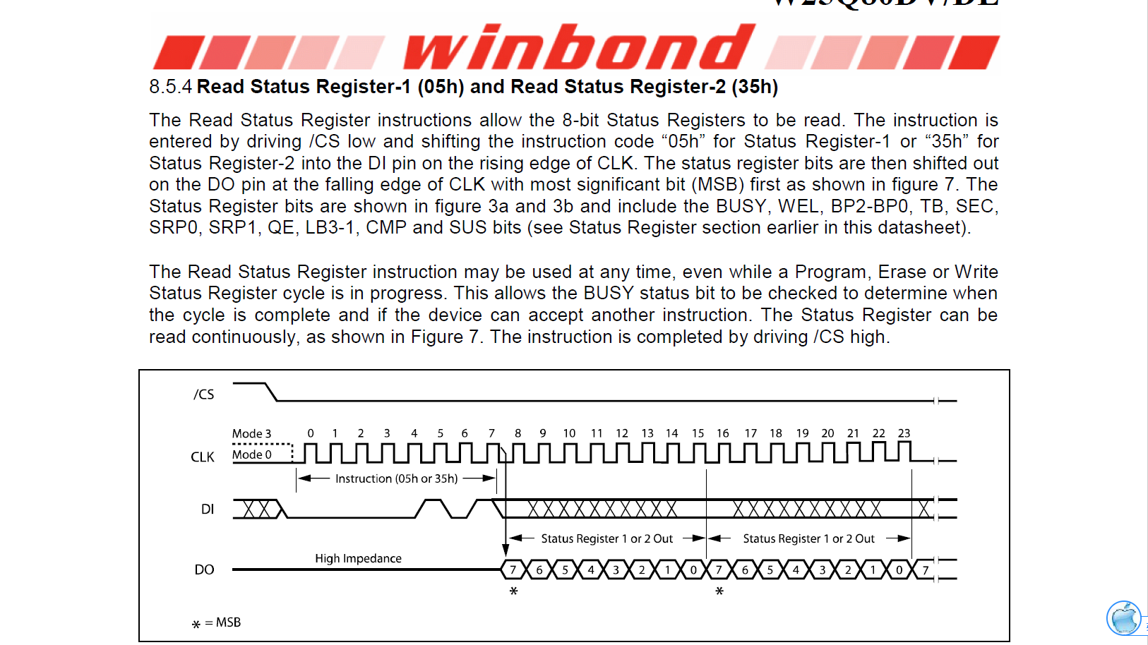
The QE bit is in status register 2. So we should use “cmd = 0x35”.
After issuing the cmd 0x35, only one byte of data on FLASH SO pin is necessary. So we should set “status_length = 1”.
In this one byte of data received, the offset of QE bit to LSB is 1. So we should set “quad_bit_offset = 1”.
- [Quad_Enable_Write]
This configuration is used to tell the bootloader the way to set Quad status of flash. The QE bit can be written by Write Status Register command.
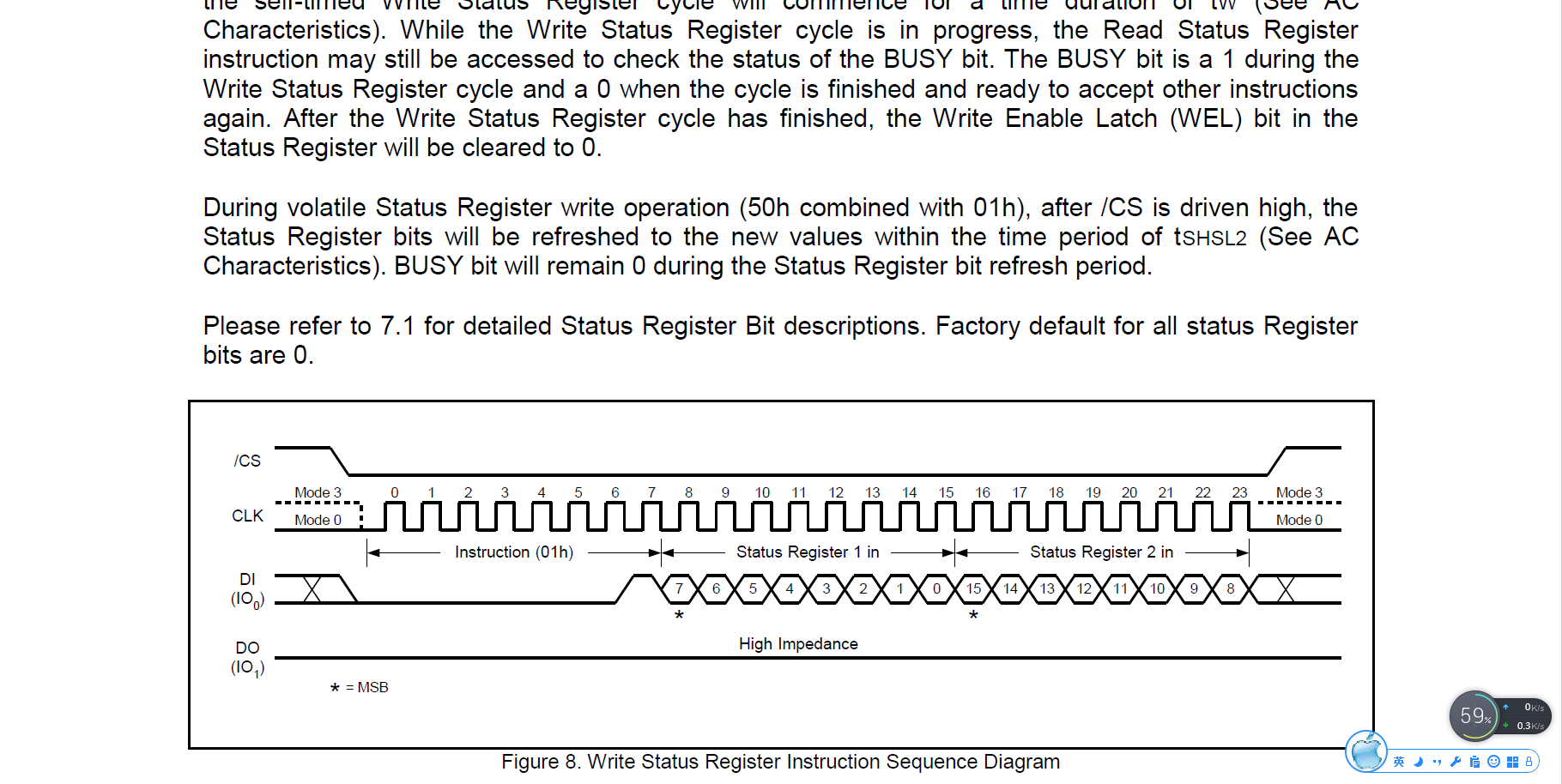
Write Status Register: “cmd = 0x01”
There are two bytes following the command. So we should set “status_length = 2”.
Before issuing the command through SPI interface, we will prepare a two-bytes-long data in memory. The QE bit will the 9th bit of this two-bytes-long data. So we should set “quad_bit_offset = 9”.
When the system boots, the bootloader will first check whether the flash allows Quad operations now according to configuration [Quad_Enable_Read]. If the flash doesn’t allows Quad operations now, it will set the QE bit according to configuration [Quad_Enable_Write]. Please note that, QE is 1 and all the other bits are 0 when issuing Write Status Register command.
Building outcome
After building the application, we will get a <target>_with_bootloader.hex and a <target>.hex in the outcome folder.
Just as its name implied, the one with bootloader is a combination of user program image and the bootloader image. This file can be used for production programming.
The other one can be used for debugging programming and Firmware OTA.
- debugging programming
- It refers to the case that the bootloader has already been programmed into the flash and only user image is needed.
- production programming
- It refers to the case that the flash is totally empty.Both bootloader and user image are needed.